 |
|


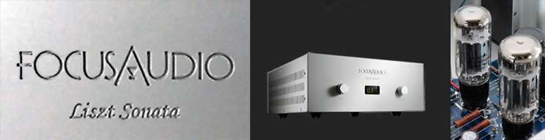
| Liszt Prelude and Liszt Sonata amplifier | |
|
|
| Design Philosophy | ||
|
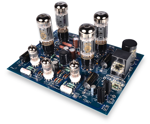
To enable music lovers as you to have ultimate listening experience, we strive to look for the best available amplifier design and components. Let us look at the four key aspects of tube amplifier design listed in their order of importance. |
||
| The Power Transformer | ||
|
|
|
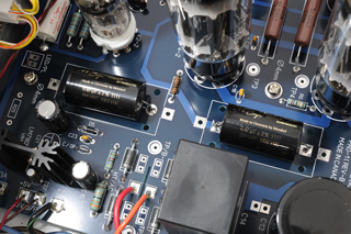
Our approach is to use a fairly small 30uf film capacitor from the German manufacturer Mundorf. This small capacitor provides a wide charging window for the rectifier and the current waveform is very close to sinusoidal with no spikes. Hence there is little RF (radio frequency) radiation to cause audio distortion. |
|||
|
One other factor that is rarely discussed is the impedance vs. frequency characteristic of the capacitor. For a several hundred uf electrolytic capacitor its impedance become inductive at 2 to 4KHZ region that is it stops behaving like a capacitor and this leaves the critical voice range to undesirable coloration. On the other hand the excellent 30uf film Mundorf capacitor still behaves like a good capacitor around 60 KHz with very linear impedance vs. frequency characteristic up to 30 KHz. |
|||
|
We use high speed rectifier with fast switching recovery time to minimize the rectifier switching noise. This together with the 30uf Mundorf film input capacitor which has very low impedance at high frequencies (about 0.0095 ohm at 57 KHz) enables us to filter out most of the noise components from the AC line and the rectifier. This allows us to hear the low level signal much better. The low impedance from the 30uf capacitor acts like a short circuit at high frequencies to shunt all the noise components to ground. We found that after we replace the first input electrolytic capacitor with the Mundorf 30uf film capacitor the background noise drop significantly. |
|||
|
 |
||||||||||
|
To summarize, the power supply is the most critical element in the amplifier design. A well designed and massive power transformer is essential for the delivery of unrestrained current supply to the amplifier. The power supply filter network must have a small time constant and minimal DC resistance to enable the power transformer to quickly charge the output capacitor to deliver the necessary current. We feel that this series of Focus amplifier with its optimized design has accomplished these goals. |
|||
| 2) |
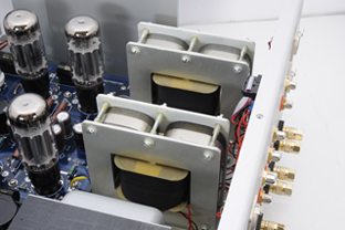
THE OUTPUT TRANSFORMER |
||
|
The law of physics in output transformer design is such that extended low frequency response and high frequency performance are two opposing requirements. To get good low frequency response you need a lot of inductance and that translates to a lot of turns in the primary winding of the transformer. To get good high frequency performance one has to minimize a parameter called leakage inductance. Leakage inductance is proportional to the square of the number of turns in the primary winding. So you can see from here that if you have a large number of turns in the primary winding for good bass response then the leakage inductance will go up and hence the high frequency response will suffer. The designer has to pick a delicate balance. The Focus engineering team has spent many months building many prototypes before they are happy with the design. |
|||
|
In the premium version of the amplifier we change the core material of the output transformer to double C core. The double C core has excellent magnetic property and that enable us to use less primary turns to achieve the same inductance and hence the leakage inductance is lower. The lower leakage inductance give us a better high frequency performance. |
|||
|
One of the parameter in output transformer design that is rarely discussed is core saturation. The manufacturer always quote you the frequency response at 1W. It looks very good but what is the response at rated power? |
|||
|
To get rated power at 20Hz you need to have a sufficiently large transformer core so that the output transformer does not saturate at low frequencies. The rule of thumb used by the Focus engineers is that if the rated output power is 35W we will use a core that is rated for 350W. With this kind of design margin we have been able to get an almost flat frequency response from 20Hz to 20 KHz at the rated power. |
|||
|
Many audiophiles complained tube amplifiers are bass shy. You are invited to audition this new series of amplifiers from Focus. With properly dimensioned output transformers and power supply you will get quick and thunderous bass. |
|||
| 3) |
THE CIRCUIT TOPOLOGY |
||
|
The output stage is a low anode voltage and high current design. It is a class AB push pull topology with very deep class A biasing so as to get the sonic benefits of class A operation and yet maintain fairly good power output efficiency. Auto biasing circuitry is employed to give best stable operation condition without the need for frequent bias adjustment. |
|||
|
The driver circuit is a cathode coupled voltage gain and phase-splitter design. It is simple and good sounding. The circuit topology has been implemented in many highly successful tube amplifier designs in the 40s, 50s and 60s by extraordinary audio engineers. Our goal is not to reinvent but to leverage the fruits left by these brilliant designers. |
|||
|
|
||||||||||||||||||||||||||||||||||
|
|
|
Copyright by Focus Audio Inc., 2002 - 2014. Best viewed by 1024 X 768 |